 Co., Ltd.")

Provider of components and system solutions in the low and high voltage power distribution field
Smart Lighting
Release Date:
2025-08-15
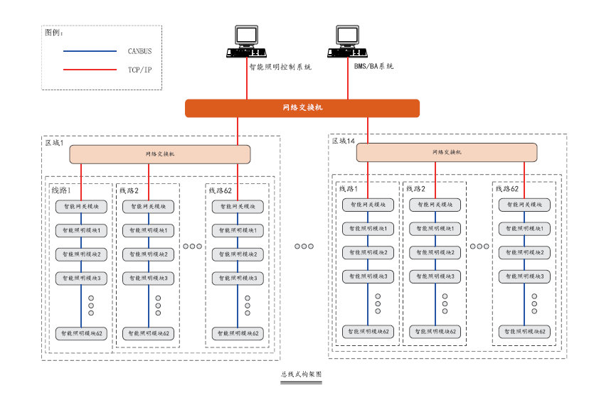
Intelligent Lighting System Network Structure
■ Device Layer
All modules in the device layer (except the power supply) have a globally unique physical address and a system-unique CAN bus address. All modules can be configured and defined through configuration software. Device layer modules can access switches or building control systems via gateway modules.
■ Line Layer V
Each line can support up to 62 device layer modules. Lines communicate with each other through network switches after protocol conversion.
■ Area Layer
The area layer can support up to 62 independent lines, i.e., 62*62 bus devices. The system can support up to 14 area layers, so the maximum device capacity of the system is 14*62*62 bus devices.
■ Physical Connection
1. The system unit module operates at DC 9-24V. After signal conversion, system device signals are connected into a network via CAT5 through switches. CAT5 communication cables should be laid separately using galvanized steel pipes or PVC pipes, and the horizontal distance from power cables should be at least 300 millimeters.
2. For a single independent line, the CAN bus should not exceed 500 meters, and the CAT5 communication distance should not exceed 100 meters. The bus distance can also be extended by using fiber optic cables.
■ Networking Characteristics
1. System lines need to be designed as linear topologies, forming multi-line systems through network switches.
2. Star and tree topologies can use CANHUB modules to solve networking topology issues, but ring structures are not allowed.
Keywords:
Continuously creating greater value for customers
Providing you with competitive products
* If you have any questions, please contact us!
Contact us now, unlimited possibilities start from the first communication!